
There is something bothering me at home. That thing is the remote control for the TV. It’s an LG Smart TV, an excellent choice of TV. The remote is fancy, with move controls, and works like a mouse or Wiimote. It’s better to type on than most common remotes. It’s a good TV in general, but with a problem that appeared recently, on one button. The most important button. The Power button. Clicking it almost never works, which is inconvenient. Using the button on the TV itself requires getting up, which goes against all reasons to have a remote. Such button is also awkward to use. This is probably the only bad part of watching TV.
How hard would it be to make a circuit with a microcontroller and an infrared transmitter to control a single function to turn the TV on and off? Easier than I thought, actually.
This is the first part of my process of concluding this project. I divided it in 3 parts:
- What the TV wants
- Making the remote
- Joining everything
Through the air
To start, my knowledge about how the remote works is:
- The remote sends an infrared (IR) message when the button is pressed
- When the TV receives the message, it turns on or off
It’s almost nothing, but it’s a start. I also remember reading about Arduino and infrared on Ken Shirrif’s blog, so I started researching there, since his posts are always well explained and very detailed. Finding this, now I have an Arduino library to send and receive infrared messages. I also know that the transmitted signal is, usually, modulated in 38kHz and that there are many different protocols. So I also need to know what protocol my TV and remote uses.
I could use the library and an Arduino to find out what is the protocol, but I decided to do it another way. I used my logic analyzer and sigrok, an open source software for this kind of analyzer, to see the signal.
Before getting to the logic analyzer and sigrok, I need an IR receptor. I already had a VS1838B receptor stashed away ready to use. Unfortunately, the datasheet is in Chinese. However, it’s possible to understand it from the images and numbers. There is a pin for VCC, a pin for GND and the middle pin the output. The circuit also includes two capacitors and a resistor. The block diagram shows that this component is more than just a receptor. It includes filters, amplifiers and a transistor to source a bigger current at the output. The numbers tell that the power supply should be between 2.7V and 5.5V and the frequency of the carrier is 38kHz, as expected. The interesting parts are the images of the signal at the input (infrared) and output (electrical signal). The input is a modulated signal with active logic level high, while the output is it’s demodulated with active logic level low.
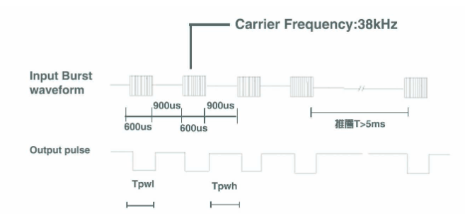
It’s worth noticing the image that shows both the modulated and demodulated signals. The input is modulated with PWM (Pulse Width Modulation). There is also a small delay between a signal arriving at the input and a demodulated output, which is expected because of the internal processing of the receptor.
My logic analyzer is a Chinese copy based on a USB microcontroller from Cypress (FX2LP series). It’s the same integrated circuit used on the Saleae Logic, a low-cost logic analyzer that was the source for the series of Chinese clones. Although it’s possible to use the Saleae software with the Chinese clones, I prefer to use sigrok. This is an open source software for signal analysis, compatible with logic analyzers, oscilloscopes and other similar equipment. Sigrok itself is available as a command line interface or with graphical user interface (GUI) called PulseView, which is the one I opted for. I only needed to install a driver for the logic analyzer to be recognized and it was ready to be used.
With the IR receptor connected to VCC and GND and channel 0 of the logic analyzer connected to the output, I could start to record the signal and press the button on the remote. The result is the beautiful image following.

Definitely there was a signal captured, but no information about it except that it exists. Zooming in to see better…

There is a train of pulses, with a big initial pulse, followed by many small pulses. After the train there is a interval between the next signal. Someone with experience on IR transmission of remote controls can get more information from this image alone, like the protocol being utilized. People without experience can look for multiple protocols and check if any matches the observed pattern. But there is a tool that helps a lot with this work.
Decoder
sigrok bundle with PulseView many protocol decoders. This translates a signal to something more comprehensible for a human, as long as the protocol is known. There is a great variety of protocols bundled with sigrok (see image below), for all kinds of applications. There is always the opportunity to add more protocols in case the one needed is not available.

What does it help without know what protocol to use? Well, look at the following image…
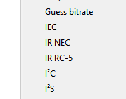
There are two IR protocols ready to use. Maybe one of these is the one I need. Trying the IR NEC protocol first and configuring the decoder to use channel 0 of the logic analyzer…
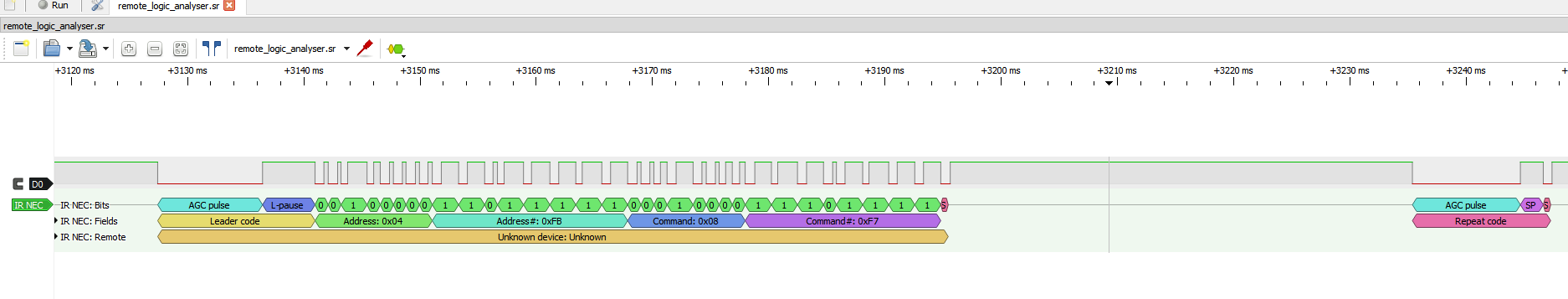
Worked on the first try! And perfectly! Something like this is rare, so be sure to enjoy this feeling while it lasts. One mystery solved: the protocol is IR NEC. First, it’s worth analyzing what is possible just from what the protocol decoder tells us. There are 5 parts that seem important here:
- Leader Code
- Address
- Address#
- Command
- Command#
Actually, only 3 of those are important. Getting ahead of myself and telling how the protocol works, Address# is the complement of Address, which mean it’s the same value with the bits inverted. All zero bits change to one and all one bits change to zero. Same foes for Command and Command#. This is a simple way to add error checking, since the receptor can check the message against its complement. If there is something different, an error occurred.
There is also the second patch on the image, after the main message. It was decoded as a Repeat code, so the receptor knows that the main message was sent twice or more. So, the main message is sent once and each following click of the same button sends a standard message to “repeat the last operation”. It’s possible to imagine it being used when someone is changing channels really fast. As the repeat code is shorter than a complete message, the risk of a button being pressed faster than the device can transmit is smaller.
After researching more about the protocol, I know it starts with a pulse signal during 9ms, followed by a pause of 4,5ms. Following it are 32bits (detailed soon) and a last pulse to indicate the end of the message, with duration of 562,5μs
To send a bit of information, the traditional way for protocols like UART or I2C is to use a logic level low to indicate a zero bit and a logic level high to indicate a one bit. The IR NEC protocol works differently. To send a bit, be it zero or one, the signal is kept at logic level high for a set duration, followed by a logic level low for another set duration. What changes between sending a zero bit or a one bit is the duration of each logic level. It also changes depending on if the system works with active-low or active-high signals. This way, it’s easier to talk in terms of bit that are not related to the way the message is transmitted, only to the contents of it. Then we have, for an active-high transmission:
- Bit 0: high pulse for 560μs, followed by a low pulse for more 560μs. Total bit duration is 1.125ms
- Bit 1: high pulse for 560μs, followed by a low pulse for more 1.6890ms. Total bit duration is 2.25ms
This method of transmission where the duration of a bit is used to define it’s value it’s called Pulse Distance Encoding (PDE). It’s important to note the difference between PWM modulation (physical transmission of the data) and PDE (how bits are represented). The encoding is “above” the modulation, since the demodulated signal is still encoded. To transmit a message, first is done the encoding, then the modulation. At the receptor, the inverse is done.
Knowing how the bits work, it’s possible to send bytes. They are sent with least significant bit (LSB) first. As seen in the initial analyzes, the destination address of the message is sent first, followed the complement of the address, the message itself and, at last, it’s complement.
This protocol is useful for low data rates, but with mechanisms to ensure the message integrity. It is also relatively simple a can be implemented using only the PWM output of a microcontroller. The next part will show how I created a transmitter with my microcontroller of choice: a MSP430 from Texas Instruments.
